Quick start
Download the inventory file  and save it in your local folder.
Follow the Demo
http://youtu.be/JeUvCHbi0Jg
ProtocolNavigator
ProtocolNavigator has three interconnected panels/windows:
1) the
inventory, defining the laboratory materials and instruments,
2) the
bench, where these materials and instruments are selected and applied to sample matrix to construct a method component according to a timeline; and
3) the
map,
where design of the experiment automatically emerges as actions are carried out at the bench.
This interactive map depicts both the experimental design (as the spatiotemporally linked patterns of actions), and the provenance trail (linking manipulations and measurements). Interfacing with the map, experimentalists can derive knowledge through navigation, interpretation, and assessment.
Importantly, the map can be shared with collaborators and produced in a textual or indeed a narrative form as part of a
publication.
Resizing the panels/windows
The panels/windows can be resized by selecting the corner or divider line and mouse dragging.
Note It is appropriate to think of ProtocolNavigator as a design board - above and beyond Laboratory Information Management System (LIMS). Because it enables user to design the whole or part of the experiment during the brainstorming session, which usually happens long before the real experiment is carried out. This design can be done from the scratch or incorporating and modifying parts of other's design.
During experimentation, drifts that occurs from the design can be easily modified and incorporated, thus the design now reflects a practice map. Indeed all experiment related information are embedded within the map akin to LIMS. Moreover saved components or the entire experiment can be reused in the future by others. This provides the capacity for prototocol exchange, adaptation, comparison and accuracy.
Tutorial
 Create inventory Create inventory
Click on element below for details in drop-down window |
|
|
In a typical laboratory before undertaking an experiment, the user gathers together the materials and reagents to execute the experiment. In addition, it is important to ensure the right instruments
are available and in the appropriate configuration. ProtocolNavigator emulates this approach in silico. Users gather and define their reagents as well as the instrument set-up. Multiple instances of materials
and instruments (termed hereafter as elements) can be created thus composing the comprehensive inventory. Presentation of instances allows for reagent variability (ie concentration dose responses), as well as
different instrument settings to be incorporated into the protocol. Once created, instances of all elements from the inventory are available on the 'shelf' of the Bench. The way ProtocolNavigator works is that
the user undertakes time-stamped actions accounting for each sample in the experiment. Hence the user adds, manipulates and acquires data from these samples whether they exist in tubes, coverslips or multi-well dishes.
There is complete flexibility of incorporating or modifying elements at anytime of the experimentation. In ProtocolNavigator, the elements are broadly grouped into two categories SETTINGS and ASSAY.
From a hypothetical point of view each element contained under the SETTINGS can be viewed as a "noun" whereas each element under the ASSAY as a "verb". For example "Centrifuge" under the SETTINGS describes the admin and or
setting specifications of a centrifuge machine, while centrifugation is considered as a process i.e. verb that uses the centrifuge machine and therefore is defined as "Centrifugation" element under the ASSAY category.
Elements within the ASSAY category can also be viewed as sub-process, where different elements like Dye being first defined and then the procedure of adding dye being described. Once created elements are readily available on the 'shelf' of the Bench
and can then be applied to the sample. Most of the elements under the ASSAY category (except Static and Timelapse Image) have the procedure embedded with it and therefore are considered as sub-process/ASSAY element.
Some of the ASSAY elements has dependency ? on SETTINGS elements and are symbolized by  icon. icon.
Some ASSAY elements can be saved and reused indicated by the  and and  icon. icon.
External files (Excel, pdf etc.) or proprietor files of instrument can be attached with some elements and are symbolized by  icon. icon. |
 Bench work Bench work
Click on element below for details in drop-down window |
|
|
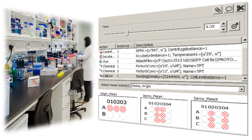
In ProtocolNavigator, the virtual Bench mimics a typical laboratory workbench, where experimentalists/users emulate their real life laboratory practice through this 'Bench' panel. Akin to reality, a given experiment consists of a set of manipulation and measurement activities that are synchronized with time.
To start with, at this virtual bench, the user has a 'shelf' of all the elements (reagents and instruments) required for the manipulation/measurement activities.
Multiple instances (capturing the variability of drug/dose, settings aspect) of these reagents and instruments created via the Inventory panel are available in this shelf. The workbench also contains the experimental vessels (e.g., plates and wells)
to which instances of reagents or instruments can be applied at given time points. A time slider is also included for time point selection. At this virtual bench, the experimentalist undertakes a step-by-step activity just as would have been performed in the real-life scenario.
As each activity in the experiment is undertaken, the program automatically depicts the design or methodological map of the experiment on the canvas based on manipulation/measurement instance (what) is applied to the location of the vessel (where) at given time point (when).
For measurements, users can link the experiment derived data (e.g. image data) within the map, which provides a visual contextualisation and provenance of the data. |
 Navigating through the map Navigating through the map
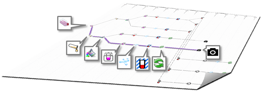
On the canvas of ProtocolNavigator a practice map is automatically drawn, based on the activity on the bench. Underpinning algorithm of ProtocolNavigator facilitates to depict the design complexity of the experiment, which otherwise could not be conveyed by conventional communication approaches. Setting design in context of time converts the map to a practice map, through which practice variation can be easily identified.
Moreover, this map acts as the access point for the action related information and experiment derived data.
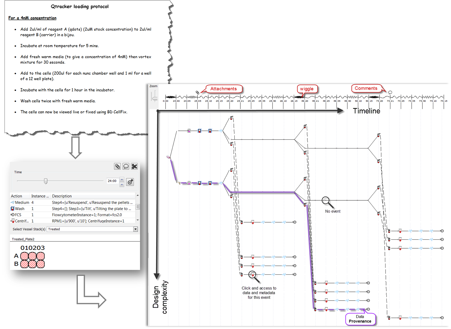
Timeline: Positioned across the top of the practice map, the timeline provides a longitudinal reference or temporal context for the map. Each time point is aligned with one or multiple action icons, indicating when that action(s) was performed. Even though all time points are equally spaced,
wiggle connecting two subsequent time points shows the time interval between two actions, and usually refers to the left hand side action(s) duration. Wiggle frequency is directly proportional to total experimental duration and dynamically change with relative to successive actions.
Practice map: Longitudinally each icon represents an action (either manipulation or measurement) that affected a set of wells (location of the experimental matrix) for that time point and dot represented set of wells unaffected at same time point. Latitudinal line represents series of actions occurred to a set of wells (location), therefore each latitudinal line becomes a "provenance trail" for sample(s) within the wells. Contrast to physical map, these latitudinal lines can diverge or converge according to the action locations, as illustrated within the carousel of the Bench work.
Time point will be set on the visualsation panel, on the Bench the location(s) will be highlighted along with the instance on the shelf and time on the slider. This will also invoke the related instance within the inventory panel to show the material information. If the action is a measurement (Data Acquisition), in addition to the above synchronization, a pop up window will appear listing the location, timing, link url and provenance (prior actions taken). Users can export this listing as *CSV and if the data are images and if ImageJ is located under the C:/Program Files folder, can be viewed directly. |
 Publish protocols Publish protocols
Users can publish the protocols at any time by clicking the Print under the file menu. The printing feature of ProtocolNavigator embraces the ethos advocated by current standardization initiatives - 'report in standard fashion', which is often perceive as burden to the experimentalist since it is double reporting and in a format that they are not familiar with.
In ProtocolNavigator, not only this burden been relieved, but we also have adopted the Google Map ethos that provides a time-stamped sequential description of steps along with a localised visual representation of the location. We are further aiming to develop the capacity to extend this output format to any journal-specific functionality, where users can generate different format of material and method section from the same protocol.
This will not only reduce the burden of creating multiple records of the same protocol, e.g., during execution (lab notebook), archiving (informal text document) and publication (formal text document), but also increase the possibility of coherent or standardized reporting of protocols. Efforts been taken to incorporate community approved vocabularies where possible to promote the establishment of standardized vocabularies and ontology. |
This element contains all the administration details of the project. This defines all the formalities such as title, purpose, ownership and affiliation of the experiment - date-stamped for archive and traceability.
A default file name is produced based on information from three mandatory fields (red coloured):

Experiment Start Date_Experiment Number_Project Title
However, the user is able to change the filename to any desired nomenclature if deemed to be more suitable.
Note It is important to select and fill all three of the above fields, this creates the filename; otherwise the filename will default to 'new experiment' upon saving.
Here the objective is to define the biological sample; in this case the cell line and its culture conditions to be used in the experiment. Multiple instances of the cell line can be created through the
 or
or  button, this provides the user with the ability to define the origin of all the different cell types to be used.
Each tab or instance represent a stock culture flask containing the sample which is defined by three sections -
Administrative Information, Biological Information and Cell History. The first two sections contain the basic or static information that defines the cell line. Information at these two sections are in alignment with those available at the ATCC
website.
The last section describes the maintenance history of the cell line within a give laboratory.
This section is dynamic and the degree of information can be changed according to the requirements of the users.
The slide carousel below describes the five core steps that defines the cell line and the relevant culture history
Flow Cytometers are more rigidly defined from laboratory-to-laboratory. Therefore, it is essential not to assume the configuration of a system. The user therefore has the opportunity to define each set-up instance of the flow cytometers to be used. Essentially, each flow cytometer consists of different components (see the panel carousel below) which in combination make up the various channels.
For the most popular flow cytometers, the components are fixed but for some flow cytometers (e.g. BD FACSVantageTM) customisation is essential.
Channel setting
ProtocolNavigator offers a modular channel building approach,implemented around the essential optical principal of light excitation and emission.
The flow cytometer components are compiled across the entire instrument from laser wavelength to the emission filters used, each component can be selected from the list in a modular fashion. Additional help is offered by adapting the prospective settings of the optical components based on previous inputs (colour assists in this process)
Note All the channel components can be added in any order according to the actual instrument, after setting the excitation laser wavelength. You can cancel the channel building process at anytime if a mistake is made. Channels can be easily deleted and rebuilt from scratch. The purpose is for users to understand at first principles the instrument configuration.
Channel components include:
- Dichroic Mirror
- Filter
- Beam Splitter
- Dye (to select Dye with the selected emission range).
- Detector
Try it Download and try examples from the Instrument Settings within the Virtual Laboratory page
Some of the elements within the ASSAY category has a 'dependency' on certain elements of the SETTINGS category. These dependency are essential to properly define these ASSAY elements.
For example, to execute elements under Instrument Process and Data Acquisition are dependent on the corresponding Instrument element under the SETTINGS category. these are easily understood once the user become familiar to the tool.The following table shows dependency links.
| ASSAY element |
depends on |
SETTING element |
| Seeding |
,, |
Cell Line |
| Centrifugation |
,, |
Centrifuge |
| Drying |
,, |
Oven |
| Incubation |
,, |
Incubator |
| Timelapse Image |
,, |
Microscope |
| Static Image |
,, |
Microscope |
| Flow Cytometry File |
,, |
Flow Cytometer |
How to establish dependency: Click to the Select button situated at the top row of respective ASSAY element, this will open a dialog showing appropriate SETTING element, with all available instances from which users can select single element.
Multiplicity: Same SETTING element can be used to create multiple instances of ASSAY element, for example, from the single Cell Line element, multiple Seeding element can be created.
Save settings can be done at any point of documentation by clicking the Save Settings button. It is saved as a text file, usually the name of the file is taken from the name field.
By clicking Load Instance button you will be enable to re-use previously saved settings. This will open a file dialog through which you can open the appropriate file for the instrument. Once uploaded, this will create a new tab/instance for the setting which can be modified as required. The modified settings can also be saved for later re-use.
![]() and save it in your local folder.
and save it in your local folder.
 icon.
icon.
 and
and  icon.
icon. icon.
icon.